
In homes and businesses alike, air compressors are indispensable tools for completing a variety of projects. Yet, in order for a compressor to fulfill its purpose, it must be correctly wired with the help of a single phase 220 volt air compressor wiring diagram. This diagram serves as an easy-to-follow guide for ensuring the installation and connection of an air compressor is accurate.
Explore the Benefits of an Air Compressor
A machine that powers tools and equipment, an air compressor can convert electricity into usable potential energy stored within compressed air. By inhaling air from the atmosphere, it can be transformed into smaller packets that have increased pressure. Once done, this high pressure is ingeniously released into a storage tank where the user can access it and utilize it to run various helpful engines.
Different Varieties of Air Compressors
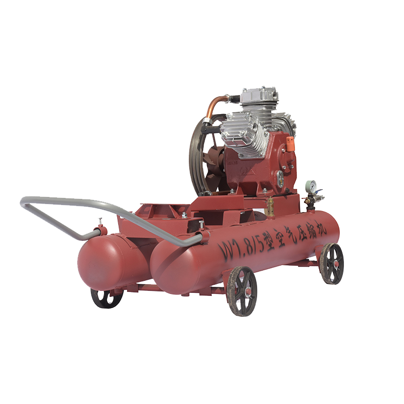
There is a diverse selection of air compressors available. These can typically be divided into single-phase and three-phase varieties. To function, single-phase models require 220 volts of electrical current, while three-phase versions need 380 volts to operate.
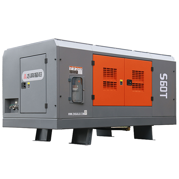
Whilst single-phase compressors are the optimal choice to power a basic home tool or reinflate some tires, larger tasks call for an increased level of compressor power; in these instances, three-phase air compressors prove to be the most powerful and desirable option. These gadgets are routinely utilised in more substantial projects, such as powering industrial air-powered machinery.
Ever wondered how to wire a single-phase 220 Volt air compressor? A wiring diagram can provide the answer! This helpful schematic diagrams how the necessary connections should be made for successful operation. It is a must-have reference for anyone looking to install and power their air compressor.
If you’re looking to install an air compressor, the single-phase 220-volt wiring diagram is a key tool. It offers a comprehensive roadmap to help you connect the compressor to power, including the needed plug type and circuit breaker/fuse specs and type of wiring required. Moreover, it will explain which breaker and fuse will work best with your setup.
If you’re looking to sync up your air compressor to your electrical system, then the wiring diagram is the place to turn. Through the diagram, you’ll get an understanding of how and which outlets are necessary for connecting the compressor to the power source.
To ensure safe usage of the compressor, the diagram of the setup will illustrate what type of wiring and connectors should be employed, as well as the appropriate circuit-breaker and fuse for safeguarding against any shorts that may occur.
Learning the Basics of Compressor Installation
To guarantee your security, it is essential to thoroughly study the single phase 220 volt air compressor wiring diagram before attempting to mount the air compressor. Although not a complex task, properly installing an air compressor nevertheless requires proper processes.
Once the wiring is looked over, the next step is to link the air compressor to its source of energy. This requires connecting the air compressor’s power cord to plug sockets wired to the energy source, as per the wiring diagram. Make sure these plug sockets are hooked up with an appointed circuit breaker and fuse.
Securely affixing the air tank to the air compressor is the next step once the power supply has been successfully coupled with the air compressor. Quickly join the air compressor’s hose to the air tank, making sure there are no leaks, and then you’ll be good to go.
To make sure that the air compressor is operable, it is necessary to test it. This process can be accomplished by starting the device and allowing it to run for a few moments. Once the compressor is up and running with no difficulties, then it is ready to be utilised.
Ensuring safety is paramount when it comes to setting up an air compressor. To achieve this, one must refer to a single phase 220 volt air compressor wiring diagram. This document is designed to help with the correct installation and connection of the device. It’s worth taking the time to review the diagram thoroughly before launching into the installation procedure. Once the connections have been confirmed, power can be supplied and the air tank can be attached. The compressor should be tested afterwards to verify that it is functioning correctly.
To ensure a successful installation and easy troubleshooting of a single phase 220 volt air compressor, you’ll need an electrical diagram that shows the wiring and components used. This wiring diagram illustrates how the components in the circuit are connected, allowing you to better identify them and understand their function. An air compressor wiring diagram is essential for ensuring you have the correct setup for your device.
Laying Out The Structure of A Single Phase 220 Volt Air Compressor Circuit Diagram
In order to understand the circuitry for a single phase 220 volt air compressor, it’s important to have a firm grasp on the components that make up the circuit. This particular set-up requires two hot wires, as well as a ground connection. Furthermore, one of the hot wires is connected to the ground to create a neutral connection. The other hot wire is connected to a motor starter that acts as a safety device for an electric motor, controlling the power supply to the motor. Finally, the motor starter is connected to an overload relay, which protects the motor from any electrical overload or runaway current. This completes the single phase 220 volt compressor wiring diagram.
A wiring diagram of a 220-volt single-phase air compressor requires the integration of some key materials. These include:
The engine of the air compressor takes center stage in its wiring diagram; it is the driving force that will grant power to all other components. This motor must be linked to a reliable energy source, either from the wall outlet or a generator.
The air compressor pressure switch is an essential component that works in conjunction with the motor, activating the motor’s turning on and off process when the pressure within the tank mirrors a specified level.
The pressure regulator is instrumental in maintaining the correct amount of pressure in the tank; it is connected to the pressure switch for this purpose. With the air compressor pressure regulator, users are able to keep the correct amount of pressure in the storage container.
In the event of a hazardous situation, the air compressor’s safety valve is designed to vent out excess pressure that has built up within the tank. Thus, it is a necessary feature that helps protect against potential disasters.
The pressure gauge connected to the pressure regulator serves one specific purpose – to monitor the pressure inside the air compressor tank.
If the pressure inside the tank of an air compressor increases beyond a certain threshold, the relief valve will be activated to discharge the excess pressure.
The air compressor tank is equipped with a drain valve, connected to the pressure regulator, that helps to release any extra pressure that has built up inside.
In order to get the motor running, wiring needs to be implemented for both power and control. For the former, attaching a power cable to the motor and then to the power source is necessary; for the latter, a pressure switch, pressure regulator, safety valve, pressure gauge, relief valve, and drain valve must each be linked up to the motor.
To properly install a single phase 220 Volt air compressor, your wiring diagram should be marked and organized before beginning. Once this is done, the necessary wiring components will need to be gathered. For your safety, make sure they are all in working order. Connect the power devices and use approved connections to add ballast, motor, and other components. To complete the installation, check the circuit breakers, wire, and ground wiring before turning the system on. When everything looks good, you’ll be able to power your air compressor and enjoy its use.
To ensure a safe and successful installation of a single phase 220-volt air compressor, it is critical to accurately follow instructions provided by the manufacturer. Each manufacturer’s instructions should include all the necessary steps for proper connection of components as well as any safety precautions that must be adhered to.
To ensure the safe operation of the motor, first attach the power cable with due diligence to avoid any electrocution of the device. Afterwards, the pressure switch should be connected to control the engine’s on/off state when the tank pressure reaches a specific mark.
After the pressure regulator is plugged in and adjusted, the safety valve should be set up. This valve is a vital component, as it is designed to let out too much pressure in the tank should an unfortunate circumstance arise. The regulator ensures the tank maintains optimal pressure, and it is connected directly to the pressure switch. Together, these two parts make sure your tank runs safely and securely.
Pressure can be kept in check with the help of a pressure gauge connected to the regulator. This device allows you to keep tabs on the tank pressure. In addition, the relief valve and drain valve should also be tied to the regulator for improved regulation of internal pressure.
Finally, the components of the air compressor- pressure switch, pressure regulator, safety valve, pressure gauge, relief valve, and drain valve- need to be linked to the motor using the control wiring. This connection is essential for ensuring optimum operation.
Troubleshooting issues with an air compressor and ensuring a correct installation can be made easier with a 220 volt air compressor wiring diagram. This diagram provides the details of the components and how they link together, allowing you to get to the root of any problems. As indicated by the manufacturer, it is crucial to take safety steps and connect each component with utmost care.
Post time: 2023-07-22
