
To ensure that an air compressor is running optimally and efficiently, one must understand the 3 phase air compressor wiring diagram. This diagram outlines the interactions between the components of the air compressor, demonstrating how they generate the required compressed air. Without this diagram, it would be near-impossible to get the most out of an air compressor for any given situation.
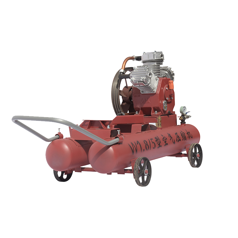
Electric energy is harnessed and utilized by air compressors to create a pressurized form of air, which is then redistributed for commercial and residential applications. From construction sites with nail guns and air hammers, to households with high-powered vacuums, pneumatic devices, and even braking systems – these handy machines drive a diverse array of tools, mechanisms, and applications.
To ensure a 3 phase air compressor properly operates, the components – motor, compressor, pressure gauge, switch, safety valve, relief valve and regulator – must be correctly powered. A 3 phase air compressor wiring diagram provides visual representation of the connections between the three electrical sources to empower the machine. As various components connect to distinct phases of the energy sources, it is vital to understand precisely where each component should be wired as to securely power the air compressor and its supplementary parts.
The heart and soul of the air compressor system is its motor, which produces the power necessary to run the compressor, which is responsible for compressing the air. Pressure is monitored using a pressure gauge, and then regulated by a pressure regulator to achieve the desired pressure. To ensure that the system does not overwork itself, a safety valve operates in tandem with the pressure switch which runs it on and off.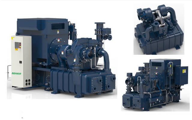
Electrical power is the driving force powering the parts of a 3 phase air compressor. To make heads or tails of the components and how they’re connected, it is helpful to get familiar with the fundamentals of electricity. We can visualize the components and their interaction via a circular diagram, each circle representing a distinct electrical phase. At the top, we have the power source which connects to the other circles, illustrating which components are linked to each phase.
The 3 phase air compressor wiring diagram provides a visual snapshot, revealing which components are linked to which part of the electrical system. It discloses the way energy is conveyed between the components, and delineates how each piece is connected. All this information is neatly presented, offering a comprehensive overview of this crucial system.
Grasp the fundamentals of using an air compressor by consulting the invaluable 3 phase air compressor wiring diagram. This critical resource is crucial for correctly installing and operating the machine and can likewise be turned to in the event of any malfunctions. Further, consulting the diagram allows for optimal usage of the air compressor, offering both safety and maximum efficiency.
To keep a three-phase air compressor functioning properly and safely, its wiring must be correctly and effectively executed. This type of air compressor is widely used for several industrial and commercial purposes – therefore, it is vital to understand the main principles behind a three-phase system before beginning to wire it up.
For industrial and commercial operations, a three-phase power system is a superior option compared to a single-phase unit; it runs more efficiently while providing the same amount of electricity. This system is made up of three alternating current sources, each displaced by 120 degrees in relation to the other two. In addition, the voltage and current are maintained in equilibrium between all three. By design, this robust solution assists with higher performance and more dependable results.
Out of the electrical systems available, the three-phase system stands out because it comprises of three wires. These are labeled L1, L2, and L3, with each carrying one of the phases. When you are wiring your three-phase air compressor, you should make sure that every one of these wires is connected to the device.
The wiring of a three-phase air compressor begins by connecting each of the three wires to the corresponding terminals. The L1 wire is linked to the L1 terminal, the L2 wire to the L2 terminal, and the L3 wire to the L3 terminal. Once this has been done, each phase needs to be tied to its respective terminal. This means that the L1 wire is connected to the compressor’s L1 terminal, the L2 wire to its L2 terminal, and the L3 wire to its own L3 terminal.
Upon attaching the three phases to the compressor, it is critical to check that the wiring is accurate. This is done through testing the voltage and current of each phase. If these readings do not match up, the circuitry must be reworked in order for the connection to function correctly. When the wiring has successfully been verified, connecting the compressor to an electricity source follows. This is achieved by connecting the three-phase wires to a power source.
Upon securing the three-phase air compressor to a power source, all that is left to do is hit the “on” switch. After activating the device, it will automatically begin to compress air and then the three-phase air compressor will be ready for use.
To bring this to a close, correctly wiring up a three-phase air compressor is not particularly difficult. As long as the connections are accurate and the compressor is correctly connected to the energy source, you’ll be good to go. Once both of these elements check out, the device should be all set and raring to go!
Post time: 2023-08-08
