
Understanding the complexities of a wiring diagram for a three-phase air compressor pressure switch is an incredibly important step in equipping oneself for a smooth and safe setup. Essentially, this diagram maps out all of the electrical pieces – such as the pressure switch, motor, and other elements – in order to function with assured efficacy. In essence, it acts as an essential guide in ensuring the most effective and secure implementation of the system.
It is essential to comprehend the fundamentals of three-phase air compressor wiring in order to utilize the system properly. This setup involves three power sources that provide electricity to the motor, which propels the compressor’s effort. All are wired to a pressure switch that governs the flow of air into the apparatus. The switch is then tied to the motor, kick-starting the compressor’s operation.
It is essential to properly wire a three-phase air compressor for it to function correctly. The power supply, pressure switch, and motor all need to be linked in the correct order and sequence. A wiring diagram will specify how the elements are to be connected, including between the motor and the pressure switch. This will guarantee that all components of the system are properly wired together to ensure the compressor operates as anticipated.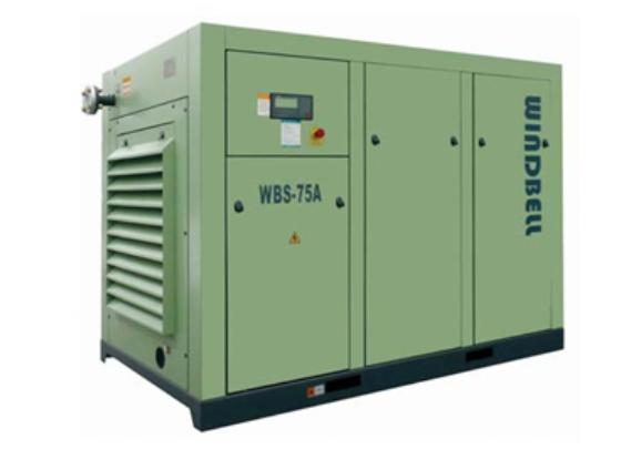
Ensuring the appropriate wiring of a three-phase air compressor is imperative, particularly that of the pressure switch. This particular component manages the air supply and requires wiring that will shut off the motor power when the pressure gets to a particular point. Thus, protecting the system from overloading, possible destruction, and undesired consequences.
When wiring up a three-phase air compressor, an essential factor to consider is the motor’s wiring. To make certain that it can safely manage the power needs of the system, it must be configured in such a way as to prevent overheating. If the motor becomes too hot, it can fail and create a hazardous situation.
It is pertinent to securely connect all the elements while wiring a three-phase air compressor, for example, the motor, pressure switch and power sources. The wires should be suitably insulated and fixed securely in place, plus regular inspections should be conducted to guarantee that the wiring is working appropriately.
Securing the reliable operation of an air compressor by methodically adhering to a three-phase air compressor pressure switch wiring diagram brings about the desired outcome of peak performance. This augments longevity and steady running, keeping hiccups to a bare minimum.
Those tasked with the task of constructing a 3 phase air compressor, as well as those maintaining the same, can do so using a pressure switch wiring diagram. This specialized diagram clearly outlines all necessary connections for the air compressor and makes setup and upkeep a breeze. An electrical blueprint, of sorts, users are offered a step-by-step guide for successful implementation and maintenance.
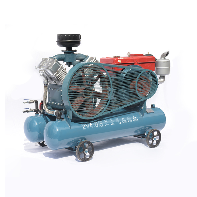
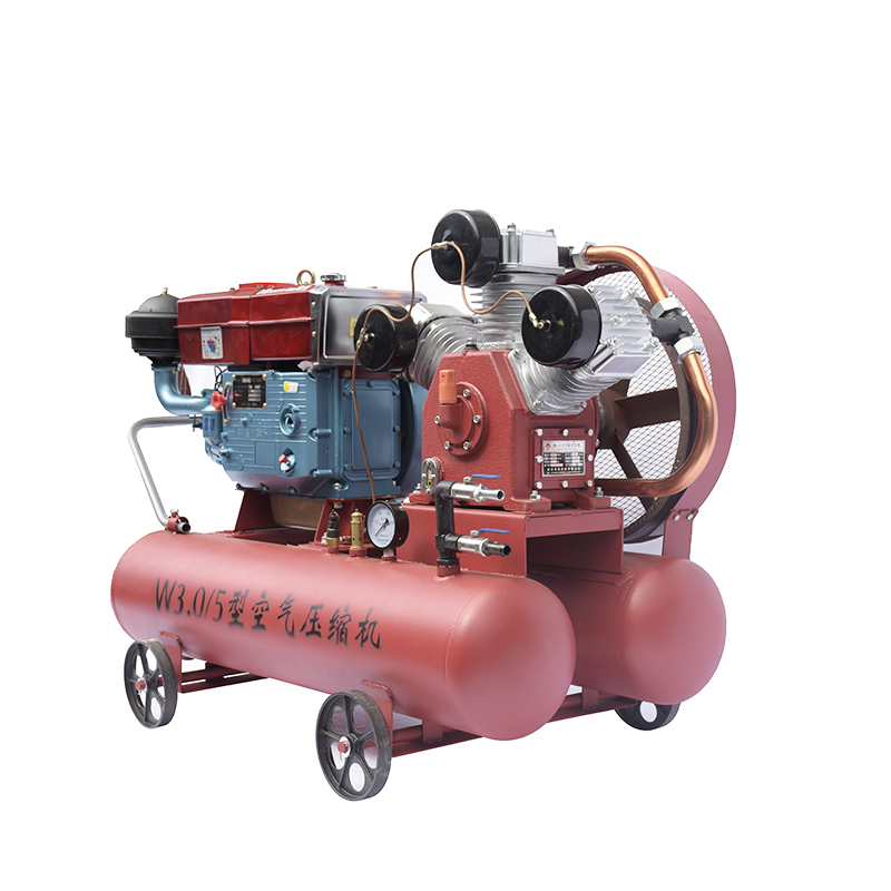
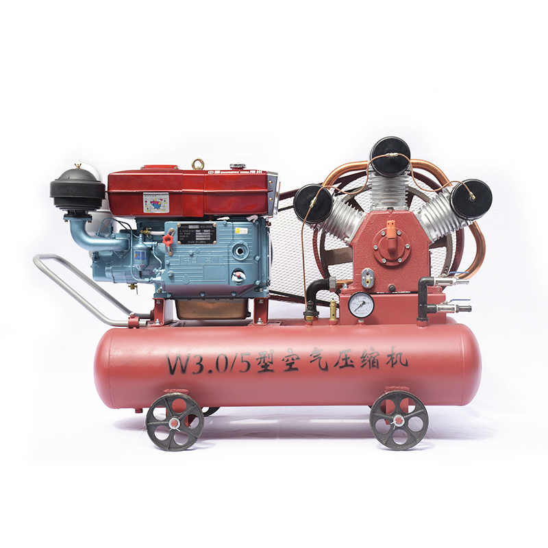
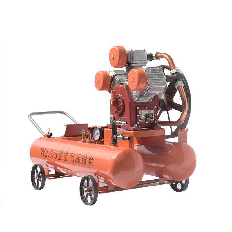
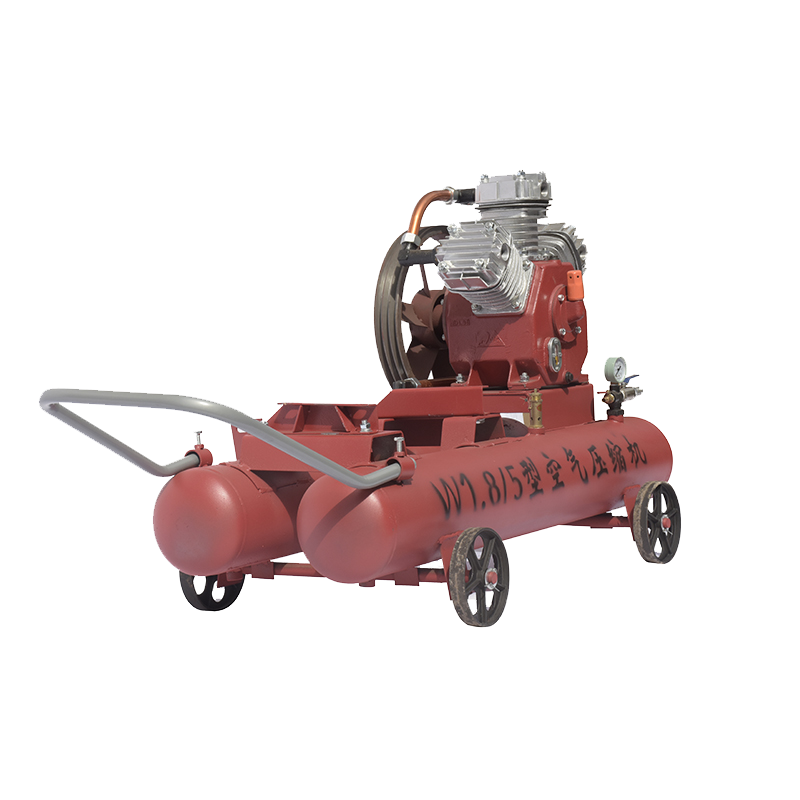
Utilizing three alternating current circuits, a 3 phase air compressor encompasses considerable power and is usually reserved for hefty industrial machines and tools. The device can even fuel air compressor pumps. A 3 phase air compressor pressure switch wiring diagram portrays diagrams of the power source, pressure switch, and associated wiring links.
The power supply is integral to the successful operation of a 3 phase air compressor pressure switch, supplying it with the electricity it needs to function properly. It must be connected to a dependable energy source, like a main power line or generator, and hooked up to the pressure switch in order to provide the required power to regulate it. Ultimately, the power supply performs a necessary role in keeping the system running smoothly.
The pressure switch is a crucial factor when it comes to the functioning of a 3 phase air compressor. It serves to maintain the pressure in the machinery by connecting a three-wire cable to the power source. The wires, usually black, red, and white, are used to connect the power supply to the switch, while the red and white cables provide imperative energy for its operation.
A 3 phase air compressor pressure switch requires two wiring connections for it to work efficiently. Generally, these are fashioned from a three-wire cable, usually black, red, and white. The black wire is responsible for supplying power to the switch, whereas the red and white wires supply the necessary power for the unit’s working.
To ensure the 3 phase air compressor is successfully activated, it is critical to securely connect all wiring connections and make sure the power supply is well-attached to the pressure switch. In other words, all electrical components must be expertly and attentively fastened for peak performance.
To ensure the 3 phase air compressor pressure switch is functioning efficiently, it is vitally important to follow the manufacturer’s guidelines during installation. Taking care to make sure the wiring connections are correctly established will assure the device is running optimally.
The efficacy of the 3 phase air compressor pressure switch can be determined by making the necessary connections then testing its operation. This procedure serves to guarantee that the device has been properly wired up and is operating correctly.
The diagrams and instructions describing how to properly and safely attach a 3 phase air compressor pressure switch are straightforward and simple. Applying them correctly ensures proper wiring and operation of the 3 phase air compressor.
Post time: 2023-08-08
